ITES China Shenzhen International Industrial Manufacturing Technology and Equipment Exhibition
- 2026
- 2025
- 2024
- All
- Mainland China
- Taiwan China
- Hong Kong China
- Germany
- Japan
- United States
- South Korea
- Italy
- Switzerland
- Sweden
.png)

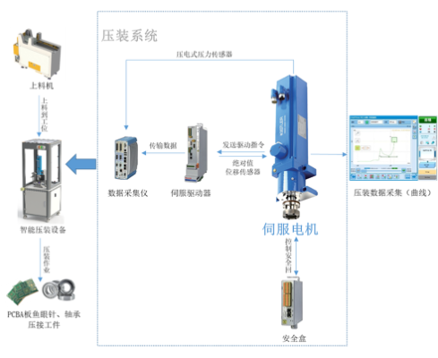
Press Fitting Ecology
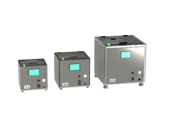
Haihou Press-Fitting Ecosystem The Haihou press-fitting ecosystem is designed for high-precision interference fit assembly between parts. It effectively controls the press-fitting depth (with a displacement precision of 0.01 mm) and press-fitting force (with a precision of 1%) while real-time data collection is performed. The system generates press-fitting process curves, which are used for monitoring and analyzing the press-fitting process.
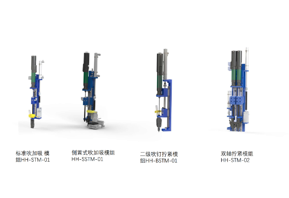
Tightening Modules
Its stable and excellent structure effectively ensures the stability of screw feeding and tightening, and can effectively solve various complex working conditions for screw tightening. Modular Structure for quick installation Compatibility with intelligent electric screwdrivers from different brands Integrated Vacuum Suction for screw feeding, ensuring reliable blow-and-suction tightening for screws of various materials Suitable for Deep Holes and Tight Spaces, meeting assembly requirements in confined areas Ensures Perpendicular Assembly of screws Full Automation when used with a screw feeder, enabling fully automated tightening
Screw Feeder
By using a stepped pusher to feed the material, screws are pushed onto a linear track, then sorted and sequentially arranged before being separated by the feeding mechanism and finally blown to the gun head. This is a prerequisite for fully automated tightening, with simple operation and maintenance that can improve work efficiency and quality management. Performance Data: Stepped Pushing Feeding: Reduces tiny particles adhering to the screws. Reduced Vibration Source: Relatively less friction between screws. Expandable Large Capacity Hopper: Reduces the frequency of refilling. 0.01% Screw Jamming Rate: Zero failures in 5 million blow-feeding cycles. Vibration-Free Storage Unit: Effectively reduces noise. Suitable for Longer Screws: Good adaptability for longer screws. Wide Screw Size Range: Suitable for screws ranging from M2 to M16, up to 70 mm in length. Multi-Channel Feeding Capability: Can support up to six feeding channels for tightening. Primary Application Areas: This system can be applied to the automatic tightening processes in the automotive, mechanical, home appliance, and electronics industries.
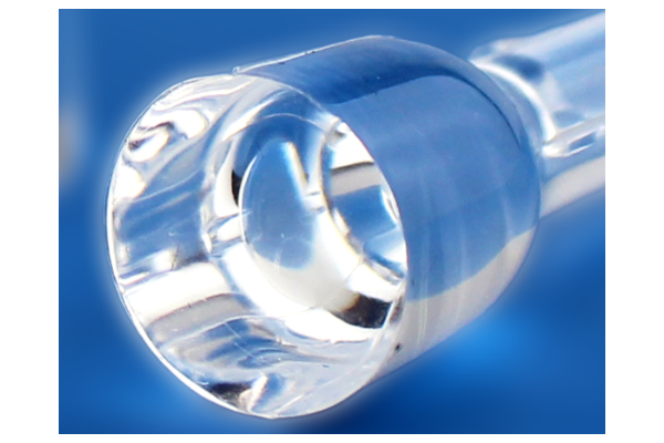
Optical Grade Liquid Silicone Parts
KinTat specialises in manufacturing high quality optical parts. Using state of the art machinery and mature processes we produce exceptionally transparent optical parts. Drawing on our experience from numerous optical parts projects we produce e.g. automobile LED parts for you. We support our customers from idea to product and process development, all the way to industrial production. Our high quality standard ensures each and every part is identical and meets your high standards as well as ours. Molding Combining this experience with our in-house mould design and toolmaking guarantee quick response times and timely delivery of all LSR injection moulding products, whatever your requirements are. Surface finishes for molds One of the key points for optical parts is the polishing of the mold. The VDI 3400 and SPI Finish are the two most widely used surface finishes for molds. They consist of 90% of finish references on the market.
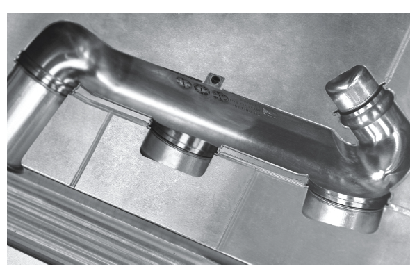
Rubber/Silicone Mold
We offer prototype, rapid and production mold tooling. All molds are fully designed in house to meet customer's specifications. The full modification, repair and maintenance facilities are equipped at the factory to ensure the molds can be quickly machined. Specialize in the following types: Compression mold Liquid Silicone Rubber(LSR) Injection mold Transfer mold Prototype mold Combining this experience with our in-house mold workshop and rubber compounding facilities, we can provide you with a one stop shop solution, whatever your requirements are.
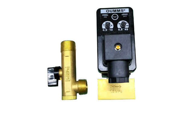
Electronic drain valve
This product is a water treatment equipment used in the air compressor industry, which can make the water produced by the cold dryer and filter discharge from the air system regularly.

Automatic drain valve
This product is a water treatment equipment used in the air compressor industry, which can automatically discharge the condensed water produced by the filter from the air system.

Pre-filter
This product is a sewage treatment equipment used in the air compressor industry, which can filter the sewage impurities produced by the cold dryer and the air storage tank to obtain clean condensate water.

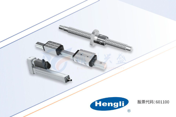
MICKEY mold spring, MICKEY nitrogen spring, Swiss-type lathe spring, pulling spring, stamping spring, automobile spring, all kinds of non-standard special-shaped spring customized
MICKEY mold spring, MICKEY nitrogen spring, Swiss-type lathe spring, pulling spring, stamping spring, automobile spring, all kinds of non-standard special-shaped spring customized

MICKEY mold spring, MICKEY nitrogen spring, Swiss-type lathe spring, pulling spring, stamping spring, automobile spring, all kinds of non-standard special-shaped spring customized
MICKEY mold spring, MICKEY nitrogen spring, Swiss-type lathe spring, pulling spring, stamping spring, automobile spring, all kinds of non-standard special-shaped spring customized